1. From the Setup tab then
click on the Sites/Doors link. Click the Control Panels tab. The Control Panel List displays.
2. Click the control panel you wish to view. The associated detail
page displays.
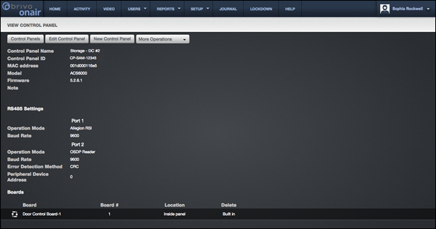
Figure 146. View Control Panel Details
This page provides links to other pages that enable you to manage
the control panel that depending up on the model may include:
Control
Panels
Edit
Control Panel
New
Control Panel
More
Operations:
Add Board
Add Wireless Gateway/Router
Add Elevator
Configure Antipassback
View Relationships
Beneath these links, the control panel details are displayed,
including:
A Control
Panel Name, assigned when the control panel was first created or last
updated by an Administrator.
The Control
Panel ID number, found with the control panel.
The MAC
address of the control panel, provided by the panel to Brivo Onair.
The control panel Model, indicating the version (ACS5000, ACS6000, ACS300, IPDC). For
ACS5000 models, this field will also indicate the type of control panel:
Ethernet or GSM.
The version of control panel Firmware installed on the control
panel.
A Note field that displays
miscellaneous information related to the functioning of the control panel, such
as where the panel is located.
For ACS6000 (dual port) and ACS300 (single
port) panels only, the RS485 Settings
section details:
Port 1 and Port 2 lists:
Operation
Mode - Port 1 can be set to either Allegion RSI or OSDP Reader. Since Allegion
NDE devices and OSDP use different protocols, the administrator needs to select
the correct operation mode. For example, the administrator cannot set the
Operation Mode to Allegion RSI and connect an OSDP reader. Port 2 will only
accept OSDP readers. ACS300 panels do not have a Port 2.
Baud
Rate – This is the speed at which information is transferred over the line. The
default is 9600.
Error
Detection Method – Allows the administrator to select either Checksum or Cyclic
Redundancy Check (CRC) as the method used for error detection.
Peripheral
Device Address – Since RS485 is a bus and several devices can coexist on the
same bus, there needs to be a method that different devices on the bus can be
sent specific messages, and peripheral device addressing solves this problem.
On the bottom half of the page, all control boards and elevators
associated with the control panel are listed. The information displayed for
each board includes:
A Board
name that is comprised of the board type and the board number, and which serves
as a link to the Board detail page.
The assigned Board #. Each of the up to 15 circuit boards in a control panel has
a unique Board #. Board #1 is always the Main Board. The other boards may be
either Door Boards or I/O Boards.
|
|
WARNING: Board # The Board # must match the address
configured on each board in the system. |

A brief description of the board’s physical Location.
A trashcan icon associated with each board listed,
if your permissions allow you to delete control boards.
The information shown for each elevator associated with the
control panel includes:
A brief, descriptive Elevator name, which serves as a link to the Elevator detail page.
The Wiegand Reader configured for the elevator.
A delete icon associated with each board
listed, if your permissions allow you to delete elevators.