1. If you are not already on the Door Control Board detail page:
2. From the Setup dropdown
menu, choose the Sites/Doors tab
then click on the Control Panels
tab. The Control Panel List displays.
3. Click the control panel for which you wish to configure a Door
Board. The Control Panel detail page displays.
4. Click the Door Board you wish to configure. The Door Control Board
detail page displays.
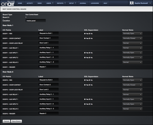
Figure 150. Configure a Door Control Board
5. The Board Type and Board # fields cannot be edited
on this page, but the Location field can be.
6. All Door Boards contain two nodes, each of which can be used to
control either one door or one door and multiple devices. On this page, these
two nodes are identified as DOOR 1 and DOOR 2, and for each there is a set of input and output points that
corresponds to a block of terminals on the actual Door Board. All of the labels
match the text silk-screened on the board.
|
|
NOTE: A Door Board node does not have to be used to control a door; it
can be used to control any number of devices. However, the following terminal
blocks cannot be used by any other device if the node is to be used for a
door: REX, DOOR CONTACT, and READER. |

7. In the Label field, accept the default label for the I/O point
displays, or accept the default Label
or enter a new short, descriptive value for the device, such as “Loading Dock
Door Lock.”
8. For each input point, there is a set of fields used to define the
operation of the associated terminals:
9. In the EOL Supervision
field, click Yes or No to indicate if the input point is wired
for end-of-line supervision. EOL supervision is not relevant for output points
(DOOR LOCK RELAY, AUX RELAY 1, and AUX RELAY 2) or for the
READER point.
10. In the Normal State field, select Normally Closed to
indicate that the I/O Point is normally closed, or Normally Open to
indicate that it is normally open. As with EOL
Supervision, this field is not relevant for output points.
11. For each output point, there is a set of fields used to define the
operation of the associated terminals.
·
In the Normal State field, select Normal
from the dropdown list to indicate that the output point operates in a fail secure
mode. Select Energized to indicate
that the output point operates in a fail open mode.
|
|
NOTE: The following three steps must be completed
in order to utilize Fail Open (Energized) functionality in Brivo Onair: 1.
Mode set to Fail Open (Energized) 2.
Correctly wired for Fail Open 3.
Fail Open style door lock must be used Simply changing mode to Fail Open from a
system that had been configured for Fail Secure operations is not sufficient
to achieve Fail Open operation. |
12. Click Save Board. You are returned to the Control Panel
detail page with the new Door Board listed in alphabetical order with the other
control boards.